Xilinx Vivado
Vivado is a streamlined set of tools for Xilinx FPGA development.
Contents
Installation[edit]
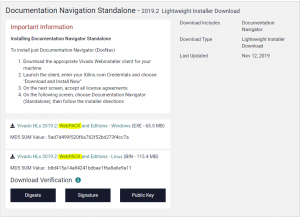
Navigate to the file server on Hive or go straight to the Vivado Download site, and scroll down to standalone installers. Grab the latest WebPack version of Vivado (See image). You may need to enter some details if using the Vivado site.
A video on installation can be found here.
Once downloaded, walk through the installation process.
- When selecting which product to install, select "Vivado".
- When selecting Vivado version, select "WebPack".
- When selecting which components to install, it is worth determining which devices you need to install for, as this can save you a large amount of download time, and space on your harddrive. For most purposes, installing just the 7 series chips (Artix-7, Kintex-7 and Spartan-7) is sufficient. You can always re-run the installer to install additional devices
- If you wish to use MATLAB and SimuLink to generate HDL, you will also want to install the "System Generator for DSP" and "Model Composer"
- Select where to install Vivado. Double check if you want to install for just the current user, or all users
- If downloading, let it run. It will likely take a while
Additional Notes for Linux[edit]
Additional steps may be required on Linux installations.
Installing Custom Board Definitions[edit]
Board definitions tell Vivado the parts and layout of the board you're using. This can be very useful when using commercial/educational boards. The process for these boards is all the same once you find the board definition files.
For a quick overview of this section, watch this video.
Note: You need to restart the IDE for new board definitions to load.
- Download the board definition file
- For Digilent Boards, you can visit the Digilent GitHub page or download all board definitions.
- Note that "old boards" are used when using Vivado 14.4 and below. Otherwise, use the new definitions. The remainder of the instructions assume you're using a version of Vivado above 2015.1.
- Navigate to where the board definitions were installed (e.g. C:\Xilinx\Vivado\2019.2\data\boards\board_files) and place the board definition folders inside
- There should be one folder per board.
- You should now be able to open Vivado and, when creating a new project, select your given board.
Creating a new project[edit]
NB: If it's your first time running Vivado, it's suggested you install the board definitions first, as the IDE needs to be restarted to load new board definitions.
A video for creating a new project can be found [here https://www.youtube.com/watch?v=dxEWSJ_jPFM].
To create a new project:
- Select "Create Project" on the main page as Vivado Opens.
- Set a project name and directory
- In most cases, the Project type will be "RTL Project"
- If you don't have any source files to start with, select "Do not specify sources at this time"
- If you have a project file, select "Imported Project"
- If you do have source files (such as Veirlog or VHDL files), you will be asked to add them
- You will then be asked for the constraints file for your board. For more information on constraint files, see below.
- Next you will be asked to select your board.
- You can select a part or a board.
- If your board is not found in the repository but there exists a board definition for it (as is the case with Digilent Boards), see the guide on installing custom definitions below.
- Finish the wizard. Your project is now created.
You will still need to set the top module, and include your constraints as the default constraint set. See below.
Understanding the Files[edit]
The Vivado File Overview[edit]
Design Sources[edit]
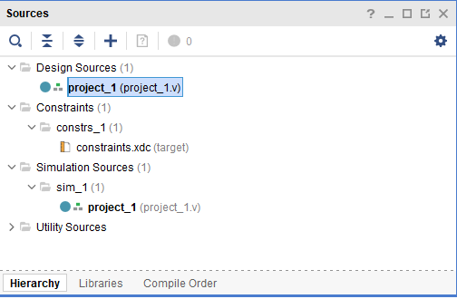
Design sources are generally the Verilog or VHDL files you will write or use in your implementation.
In order to correctly synthesize the design, you need to set a top level module (TLM). You can do so by right clicking on the desired TLM, and click "Set as Top".
Constraint Files[edit]
Constraint files list constraints in the project, and also allow you to initialize and refer to pins in your HDL. You also need to ensure you set your constraint files as being for the target board. Right clock on the constraints file and select "Set as Target Constraint File". Below is a snippet of the Nexys A7 constraints file:
# Clock signal
set_property -dict { PACKAGE_PIN E3    IOSTANDARD LVCMOS33 } [get_ports { CLK100MHZ }]; #IO_L12P_T1_MRCC_35 Sch=clk100mhz
create_clock -add -name sys_clk_pin -period 10.00 -waveform {0 5} [get_ports {CLK100MHZ}];

set_property -dict { PACKAGE_PIN J15   IOSTANDARD LVCMOS33 } [get_ports { SW[0] }]; #IO_L24N_T3_RS0_15 Sch=SW[0]
set_property -dict { PACKAGE_PIN L16   IOSTANDARD LVCMOS33 } [get_ports { SW[1] }]; #IO_L3N_T0_DQS_EMCCLK_14 Sch=SW[1]

set_property -dict { PACKAGE_PIN H17   IOSTANDARD LVCMOS33 } [get_ports { LED[0] }]; #IO_L18P_T2_A24_15 Sch=LED[0]
set_property -dict { PACKAGE_PIN K15   IOSTANDARD LVCMOS33 } [get_ports { LED[1] }]; #IO_L24P_T3_RS1_15 Sch=LED[1]
This short constraints file enables the 100 MHz clock called "CLK100MHZ", and a two-bit "array" of switches called "SW" and LEDs called "LED". One could reference these in a Verilog module as follows:
module project_1(
    input	CLK100MHZ,
    input[1:0] SW,
    output reg [1:0] LED
    );


    always @(posedge CLK100MHZ) begin
        LED[0] <= SW[0];
        LED[1] <= !SW[1];
    end

endmodule
Simulation Sources[edit]
Simulation Sources consist of "sets". Each set is a new simulation. You can read more about simulating your design lower in this article.
Running Your HDL[edit]
In order to run the HDL on the FPGA, you need to follow a few steps. The general process in Vivado is shown in the figure below. Throughout any of these steps, you can see if Vivado is busy running a job by looking in the top left corner.
Writing HDL[edit]
See pages on writing Verilog and VHDL (coming eventually).
Synthesize[edit]
To synthesize your design, you can press F11, or use the command window on the left hand side of the Vivado IDE.
Simulate[edit]
There are multiple means for simulating HDL code. For details, visit HDL Simulation.
Implement[edit]
"Vivado implementation includes all steps necessary to place and route the netlist onto device resources, within the logical, physical, and timing constraints of the design. " (From the Vivado Manual on Implementation)
Implement your design by selecting "Implement design" on the left hand side of the Vivado IDE.
Implementation Details[edit]
Here you can get details on resource usage, power consumption, timing, and other useful information.
Once implementation is run, you can view general details under the "Design Runs" Tab.

For a more detailed breakdown of the information, open a report under the "reports" tab. For example the "place_report_utilization" under "Place Design" in the Reports tab will give you detailed information on the following:
1. Slice Logic
1.1 Summary of Registers by Type
2. Slice Logic Distribution
3. Memory
4. DSP
5. IO and GT Specific
6. Clocking
7. Specific Feature
8. Primitives
9. Black Boxes
10. Instantiated Netlists
Generate bitstream[edit]
This is done by pressing "Generate Bitstream" on the left hand side of the Vivado IDE.
Programming the FPGA[edit]
To program the FPGA, do the following:
- Connect the board and turn it on
- Select "Open Hardware Manager" on the left hand side of the Vivado IDE.
- Click "Open Target" and "Auto Connect"
- Once the bitstream is generated, you can program the FPGA
Xilinx Vivado IP[edit]
IP Cores are pre-written blocks of logic that you can import in to your project. Some examples include floating point mathematics modules, communication protocols, memory modules, and queues.
Generating IP Cores[edit]
While IP blocks will abstract quite a bit away for you, you need to be knowledgeable of the IP that you're wanting to use - for example you can't import RAM IP if you don't understand certain features and qualities of the memory. To generate IP, select "IP catalog" on the left hand side of the IDE and search for whatever IP you might want to use.
Instantiating IP Cores[edit]
Once you've generated the IP, you can get a template for instantiation.
- Under the sources tab, select "IP Sources"
- Click the arrow on the right hand side of the IP core you have to open the drop down menu
- Under "Instantiation template", select the correct one for your HDL (VHDL/Verilog)
- Copy paste the template to where you need to instantiate it.


